Our Brands

Cost, Speed, & Reliability Tradeoffs between N+1 UPS Configurations

White Paper 234 Summary     Revision 2     By Wendy Torell

There is an increasing trend towards N+1 UPS architectures – rather than 2N – as IT fault tolerance through software continues to improve. There are two common ways N+1 can be achieved: paralleling multiple unitary UPSs together or deploying a single UPS frame with multiple internal modules configured for N+1 redundancy (see figure).

In this paper, we will clarify the different methods of achieving N+1 redundancy of your UPS system(s), quantify the capital cost, deployment time, efficiency, and reliability tradeoffs, and discuss the importance of fault tolerance within the UPS to ensure reliability, availability, and maintainability needs are met.

Capex comparison

In general, the more redundancy built into a UPS configuration, the costlier it will be. But it can be challenging for data center managers to make the business case for a particular level of redundancy.  We performed a capital cost analysis of three configurations (a baseline N configuration, N+1 parallel redundant, and N+1 internal “modular” redundant), to help decision makers weigh the cost / benefit tradeoffs.

The internal “modular” redundant configuration was $482/kW vs. $660/kW for parallel redundant configuration, or $178/kW (26.9%) lower in capital cost. The baseline configuration capital cost was $453/kW, or $29/kW (6.1%) lower than internal “modular” redundancy. While there is a cost per kW difference between small and large capacity UPSs, this provides a reasonable guideline for the relative cost difference between approaches.

Speed of deployment

There are also implications to the speed of deployment. A typical installation of a 1 MW UPS requires a span of approximately 6-8 weeks (which includes buffers between critical steps). The main activities that occur during this timeframe include: prepping of the room, delivery and rigging, running conduits for the UPS, pulling the wires and making the terminations, and scheduling startup and testing. These installation steps are the same for the 1N design and the internal “modular” redundant UPS, with the exception of adding an extra power module in the frame. Therefore, the installation costs are roughly the same. For a parallel redundant UPS configuration, where large UPSs must be paralleled together, the typical deployment time increase is on the order of 1 – 2 weeks or 25%-30% longer for a paralleled system. The additional field work that goes into the multi-unit installation to setup, configure, and ensure communication between units includes: more terminations for more electrical feeds, more units to set in place, more units to startup, more units to load bank test, paralleling and sync checks, more procedures to test/perform, and more control wiring and monitoring points.

With a modular UPS, where multiple internal “modules” are used to increase capacity or redundancy, this work list above is done in a factory setting, which not only saves time but also improves predictability of the result. In addition to the quicker initial install, modular UPSs offer the benefit of being able to scale capacity over time with minimal work that takes only hours vs. the days or weeks for the wiring, cabling, and commissioning work to add new UPSs to a non-modular design.

Efficiency impact

The energy efficiency of a UPS is dependent on the load it operates at. And since adding redundancy means adding extra (spare) capacity, redundancy can have an impact on efficiency. For instance, a 1N configuration consisting of (4) 250 kW modules for 1000 kW system capacity may operate at 80% load (typical threshold set by operators). An internally “modular” redundant UPS with (5) 250 kW modules has 1250 kW of capacity, which would be equivalent to 64% load, and a parallel redundant (2+1) UPS configuration with (3) 500 kW units has 1500 kW of capacity, or 53% load.

The efficiency of any particular UPS at low loads, however, varies from manufacturer to manufacturer, and model to model, and should be investigated as part of the planning process. White Paper 108, Making Large UPS Systems More Efficient, provides more background on efficiency curves and the impact operating points have on energy. In addition, a TradeOff Tool (UPS Efficiency Comparison Calculator) is available to help contrast two different UPS curves to see the efficiency and electricity cost implications.

When energy cost is an important decision criterion, it is important to evaluate the UPSs at the expected operating load. The more redundancy added into the configuration, the lighter the operating load percentage.

Risk tolerance

Every data center has its own level of risk tolerance based on the criticality of the applications it supports. Based on the IT technologies deployed, an understanding of hardware downtime costs to the business (both quantitative and qualitative), the cost premium(s) for the different UPS configurations, and the availability improvements, a decision can be made as to the appropriate level of UPS redundancy.

With a 1N design, any failure within the UPS or its batteries results in a transfer to static bypass. In this mode of operation, a utility failure would bring down the IT hardware.

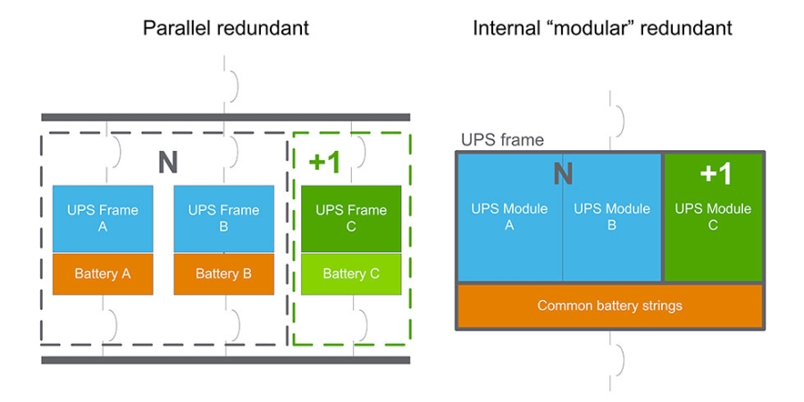
With internal “modular” redundancy, there is now a spare power module, so that a failure within a single module does not require a transfer to static bypass. Instead, the individual module takes itself offline, while the load remains backed up by the other active modules. The failed module can be replaced later by placing the entire UPS on wrap-around bypass. There are, however, single points of failure in this design. For instance, a failure with the battery system (like a battery breaker tripping) would force a transfer to static bypass, since there is only a single battery bank. Likewise, if the UPS required preventive maintenance, the load would be switched to static bypass or wrap-around bypass, both unprotected from battery.

With a parallel redundant UPS configuration, there is added protection from downtime. Because there are multiple independent UPSs with their own battery strings, the load can remain on protected UPS power during a failure within a single UPS or its batteries. A new risk, however, is introduced, with the controls, communication, and cable impedances to ensure the load is shared across the UPSs.

Fault tolerance is what enables a system to continue operating (in this case, supporting the IT load) in the event of the failure of some of its components. With that said, some UPSs are designed with higher levels of fault tolerance than others. When selecting a UPS, it is important to consider the fault tolerance design attributes of the box; especially if the chosen architecture consists of a single UPS frame. Examples of fault tolerance design attributes include redundancy of power modules, fans, power supplies in controller, communication bus, and control system. By addressing the critical single points of failure in traditional UPS systems, data centers that once required higher levels of redundancy (like 2N), may be able to rely on these mechanisms to keep critical loads operational. 

For more information on this topic including further details and assumptions on the capex analysis and efficiency comparison, please download White Paper 234, Cost, Speed, and Reliability Tradeoffs between N+1 UPS Configurations.

Download White Paper 234 Now
Learn more about modular N+1 UPS solutions
Go back to our top White Papers
Browse the entire White Paper Library

Need help?

Support Center

Obtain answers on your own by trying our digital support tools.

Search FAQs

Get answers you need by browsing topic-related Frequently Asked Questions (FAQ).

How to buy?

Easily find the nearest APC Reseller or Distributor in your location.

Find your replacement battery

Find the genuine APC Replacement Battery for your UPS.

Contact Us

Connect with us for help choosing the right product or with troubleshooting and installation. Monday-Friday between 8am – 8pm EST