Our Brands

Comparing UPS System Design Configurations

White Paper 75 Summary     Revision 4     By Kevin McCarthy, EDG2 Inc. and Victor Avelar

There are five principle UPS system design configurations that distribute power from the utility source of a building to the critical loads of a data center. The selection of the appropriate configuration or combination thereof for a particular application is determined by the availability needs, risk tolerance, types of loads in the data center, budgets, and existing infrastructure. This paper will focus on these five configurations; the advantages and disadvantages of each are discussed. The impact on availability is addressed for each configuration and guidelines are provided for choosing the appropriate design.

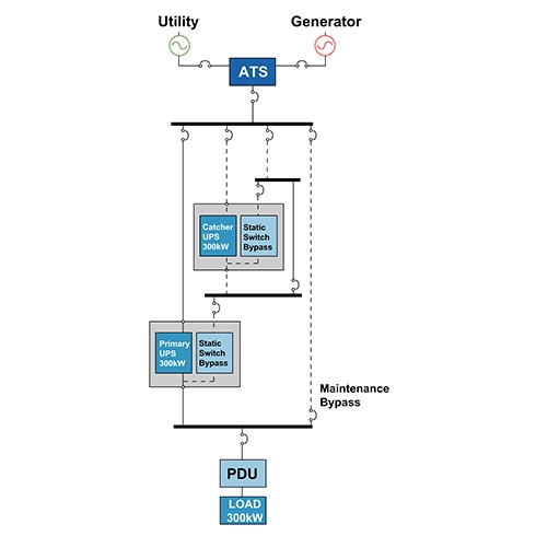
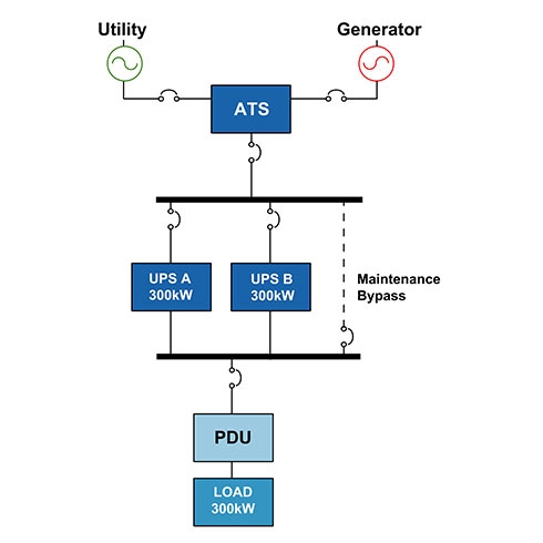
Over time, many design engineers have tried to create the perfect UPS solution for supporting critical loads, and these designs often have names that do not necessarily indicate where they fall in the spectrum of availability. “Parallel redundant”, “isolated redundant”, “distributed redundant”, “hot tie”, “hot synch”, “multiple parallel bus”, “system plus system”, “catcher systems, and “isolated parallel” are names that have been given to different UPS configurations by the engineers who designed them or by the manufacturers who created them. The problems with these terms are that they can mean different things to different people, and can be interpreted in different ways. Although UPS configurations found in the market today are many and varied, there are five that are most commonly applied. These five include: (1) capacity, (2) isolated redundant, (3) parallel redundant, (4) distributed redundant and (5) system plus system. We now describe each of these.

Capacity or “N”

A Capacity or “N” system, is comprised of a single UPS module, or a paralleled set of modules whose capacity is matched to the critical load projection. This type of system is by far the most common of the configurations in the UPS industry. The small UPS under an office desk is an N configuration. Likewise, are large computer room with a design capacity of 400 kW is an N configuration whether it has a single 400 kW UPS, or two 200 kW UPS paralleled onto a common bus. An N configuration can be looked at as the minimum requirement to provide protection for the critical load. Most “N” system configurations, especially under 100 kW, are placed in buildings with no particular concern for the configuration of the overall electrical systems in the building. In general, buildings’ electrical systems are designed with an “N” configuration, so an “N” UPS configuration requires nothing more than that to feed it.

Isolated redundant

Isolated redundant configurations (see figure) is sometimes referred to as an “N+1” system, however, it is considerably different from a parallel redundant configuration which is also referred to as N+1. The isolated redundant design concept does not require a paralleling bus, nor does it require that the modules have to be the same capacity, or even from the same manufacturer. In this configuration, there is a main or “primary” UPS module that normally feeds the load. The “isolation” or “secondary” UPS feeds the static bypass of the main UPS module(s). This configuration requires that the primary UPS module have a separate input for the static bypass circuit. This is a way to achieve a level of redundancy for a previously non-redundant configuration without completely replacing the existing UPS.

In a normal operating scenario, the primary UPS module will be carrying the full critical load, and the isolation module will be completely unloaded. Upon any event where the primary module(s) load is transferred to static bypass, the isolation module would accept the full load of the primary module instantaneously. The isolation module has to be chosen carefully to ensure that it is capable of assuming the load this rapidly. If it is not, it may, itself, transfer to static bypass and thus defeat the additional protection provided by this configuration. Reliability gains from this configuration are often offset by the complexity of the switchgear and associated controls.

Parallel redundant or “N+1”

Parallel redundant or “N+1” configurations (see figure) allow for the failure of a single UPS module without requiring that the critical load be transferred to the utility source. This configuration consists of paralleling multiple, same size UPS modules onto a common output bus. The system is N+1 redundant if the “spare” amount of power is at least equal to the capacity of one system module; the system would be N+2 redundant if the spare power is equal to two system modules; and so on. Parallel redundant systems require UPS modules identical in capacity and model. The output of the modules is synchronized using an external paralleling board or in some cases this function is embedded within the UPS module itself. In some cases, the paralleling function also controls the current output between the modules. There are logical maximums for the number of UPS modules that can be paralleled onto a common bus, and this limit is different for different UPS manufacturers. The UPS modules in a parallel redundant design share the critical load evenly in normal operating situations. When one of the modules is removed from the parallel bus for service (or if it were to remove itself due to an internal failure), the remaining UPS modules are required to immediately accept the load of the failed UPS module. This capability allows any one module to be removed from the bus and be repaired without requiring the critical load to be connected to straight utility.

Distributed redundant

Distributed redundant configurations (see figure), also known as tri-redundant, are commonly used in the large data center market today especially within financial organizations. This design was developed in the late 1990s in an effort by an engineering firm to provide the capabilities of complete redundancy without the cost associated with achieving it. The basis of this design uses three or more UPS modules with independent input and output feeders. The independent output buses are connected to the critical load via multiple PDUs. In some cases, STS are also used in this architecture. From the utility service entrance to the UPS, a distributed redundant design and a system plus system design (discussed in the next section) are quite similar. Both provide for concurrent maintenance, and minimize single points of failure. The major difference is in the quantity of UPS modules that are required in order to provide redundant power paths to the critical load, and the organization of the distribution from the UPS to the critical load. As the load requirement, “N”, grows the savings in quantity of UPS modules also increases. Overall, distributed redundant systems are usually chosen for large multi-megawatt installations where concurrent maintenance is a requirement and space is limited. UPS module savings over a 2N architecture also drive this configuration.

Configurations
Historical uses
Reasons for use
Capacity (N) • Small businesses • Businesses with multiple local offices • Businesses with geographically redundant data centers • Reduce capital cost and energy cost • Support for lower criticality applications • Simple configuration and installation • Ability to bring down load for maintenance
Isolated redundant • Small to medium businesses • Data centers typically below 500 kW of IT capacity • Improved fault tolerance over “1N” • Ability to use different UPS models • Ability to increase future capacity
Parallel redundant (N+1) • Small to large businesses with data centers typically below 500 kW of IT capacity • Improved fault tolerance over “1N” • Ability to increase future capacity
Distributed redundant catcher • Large businesses with data centers typically above 1 MW of IT capacity • Ability to use different UPS models • Ability to add more capacity • Reduced UPS expense vs. 2N
Distributed redundant with STS • Large enterprises with data centers greater than 1 MW • Concurrent maintenance capability • Reduced UPS expense vs. 2N
Distributed redundant without STS • Large collocation providers • Reduced UPS expense vs. 2N • Increased savings over designs with STS
System plus system 2N, 2(N+1) • Large multi-megawatt data centers • Complete redundancy between side A & B Easier to keep UPS systems evenly loaded

“System plus system”, “isolated parallel”, “multiple parallel bus”, “double-ended”, “2(N+1)”, “2N+2”, “[(N+1) + (N+1)]”, and “2N” are all nomenclatures that refer to variations of this configuration. With this design, it now becomes possible to create UPS systems that may never require the load to be transferred to the utility power source. These systems can be designed to wring out every conceivable single point of failure. However, the more single points of failure that are eliminated, the more expensive this design will cost to implement. Most large system plus system installations are located in standalone, specially designed buildings. It is not uncommon for the infrastructure support spaces (UPS, battery, cooling, generator, utility, and electrical distribution rooms) to be equal in size to the data center equipment space, or even larger. This is the most reliable, and most expensive, design in the industry. It can be very simple or very complex depending on the engineer’s vision and the requirements of the owner.

For more details on each of these configurations and for an appendix that quantifies the availability differences between configurations, please download White Paper 75, Comparing UPS System Design Configurations.

Download White Paper 75 Now
Learn more about UPS solutions
Go back to our top White Papers
Browse the entire White Paper Library

Need help?

Support Center

Obtain answers on your own by trying our digital support tools.

Search FAQs

Get answers you need by browsing topic-related Frequently Asked Questions (FAQ).

How to buy?

Easily find the nearest APC Reseller or Distributor in your location.

Find your replacement battery

Find the genuine APC Replacement Battery for your UPS.

Contact Us

Connect with us for help choosing the right product or with troubleshooting and installation. Monday-Friday between 8am – 8pm EST